Diagnostic Breakout Switch Board: USB Connectors, B-Female and A-Female


- Pass-through test board with inline switches
- Contains USB 2.0 connectors (B-Female and A-Female) for convenient inline insertion
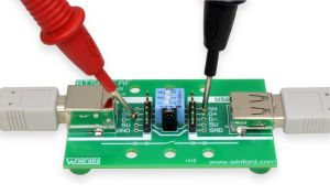
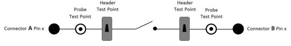
- Includes Probe test points and Header test points for every signal
- Includes switch for each data signal line and shield
- Includes jumper for the 5V power signal
- Ground connection is NOT switched
- Clearly labeled with connector pin names
- Mounting Options: Rubber Feet or DIN Rail
General Description
Insert this diagnostic Breakout Test Board into existing cable connections and get access to signals via test points and headers; this is the pass-through function of this board. In addition, switches allow individual signals to be disconnected from the circuit, which aids in diagnostics, troubleshooting, fault tolerance testing, or re-routing specific signals within a cable. This compact design is meant to be inserted into the cabling of a system during operation. Normal system operation can continue while signals are probed and manipulated. It is a handy test point breakout board with inline interruptor switches.
This board contains dual USB connectors (B-Female and A-Female). This connector selection generally allows for very convenient insertion into existing cable configurations, without the use of gender changers, etc.
A typical USB cable includes two power signals (5V and Ground) as well as two data signals and shield. With this Breakout Test Board, the two data signals and shield signal can be opened or closed using the DIP switches. In order to handle the required current, the 5V power signal is opened or closed using a jumper that is easily removed or placed as needed.
The ground signal is always connected, and is not switchable. This is because of the risk that a USB port or device may be damaged if the ground connection is opened up (depending on the specifics of the application).
This device uses USB 2.0 connectors. These connectors do not include the extra pins used in USB 3.0 connectors.
 Click image to enlarge.
Applications
- Signal monitoring or measurement
- System Calibration
- Diagnostics, troubleshooting, and debugging
- Signal injection and fault tolerance testing
- Re-routing selected connector signals
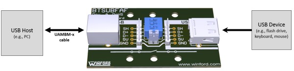
In a typical test application, the USB device being tested (mouse, flash drive, etc) would be connected to the USB-A connector on the BTSUBFAF diagnostic breakout board. A cable such as UAMBM-x would provide the connection from the USB-B connector to the port on the USB host (e.g., computer).
 Click image to enlarge.
Need something different? We stock a variety of USB breakout board styles and form factors. Please have a look!
A breakout test board may also be referred to as a "measurement breakout", "pass-through board", "test breakout", "inline test adapter", or "breakout testing board".
Product Documents
| Part # | Description | PDF Drawing | DWG Drawing | IGES Model | STEP Model | App Note |
|---|---|---|---|---|---|---|
| BTSUBFAF-R-DIN | USB A/B Diagnostic Board, DIN Mount | |||||
| BTSUBFAF-R-FT | USB A/B Diagnostic Board, Rubber Feet | |||||
| BTS Series | Breakout Test Board Application Note |
USB A/B Diagnostic Board, DIN Mount
USB A/B Diagnostic Board, Rubber Feet
Breakout Test Board Application Note
Mounting Options
These products are available in two different mounting variants. Product numbers ending with -DIN come with DIN clips already installed and ready to snap onto 35mm or 32mm DIN rail. Product numbers ending with -FT have stick-on rubber feet installed on the bottom side, allowing for benchtop use or panel mounting. For mounting the board on a chassis / panel, we suggest using 1/4" nylon standoffs under the mounting holes, and #6 screws. This provides space under the board, to keep the bottom-side pin solder joints up off the chassis.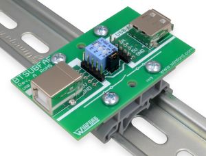
BTSUBFAF-R-DIN
Click image to enlarge. Rail not included
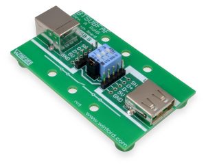
BTSUBFAF-R-FT
Click image to enlarge.Product Details
- Pass-through test board with inline switches
- Contains USB 2.0 connectors (B-Female and A-Female) for convenient inline insertion
- Includes Probe test points and Header test points for every signal
- Includes switch for each data signal line and shield
- Includes jumper for the 5V power signal
- Ground connection is NOT switched
- Clearly labeled with connector pin names
- Approximate dimensions: 2.7" x 1.6"
- Mounting Options: Rubber Feet or DIN Rail
Pricing and Ordering
| Product # | Description | 1+ | 10+ | RoHS | Buy Now |
|---|---|---|---|---|---|
| BTSUBFAF-R-DIN | USB Breakout Test Board with Switches, Right Angle Connectors (B Female and A Female), DIN Mount | $28.35 | $25.70 | Yes | |
| BTSUBFAF-R-FT | USB Breakout Test Board with Switches, Right Angle Connectors (B Female and A Female), Feet | $26.75 | $24.10 | Yes |
| Quantity | Price |
|---|---|
| 1+ | $28.35 |
| 10+ | $25.70 |
| Quantity | Price |
|---|---|
| 1+ | $26.75 |
| 10+ | $24.10 |
All of the above items are normally stocked. Please call us if you need to verify availability for a specific quantity, or for pricing at higher quantities. Please visit our ordering page for our ordering policies and a list of ordering methods.